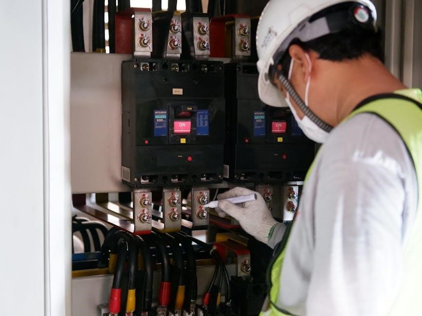
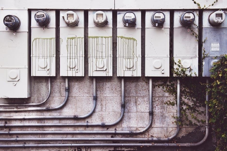
An electrical panel wiring diagram is a visual representation of an electrical panel’s components and connections, essential for safe and efficient installation and maintenance․ It provides a detailed guide for understanding complex circuits, ensuring compliance with safety standards, and troubleshooting issues․ This diagram serves as a roadmap for technicians to identify components, trace wire pathways, and perform repairs effectively․ Its precision ensures the electrical system operates reliably, making it indispensable for both professionals and DIY enthusiasts․
1․1 Importance of Wiring Diagrams in Electrical Systems
Wiring diagrams are crucial for ensuring safety and efficiency in electrical systems․ They provide a clear guide for technicians to understand circuit connections, trace wire pathways, and troubleshoot issues․ Diagrams prevent electric shock by specifying proper connections and grounding․ They also ensure compliance with safety standards, reducing risks during installation, maintenance, and repairs․
1․2 What is an Electrical Panel Wiring Diagram?
An electrical panel wiring diagram is a detailed schematic illustrating the connections and components within an electrical panel․ It shows how wires, circuit breakers, and terminals are interconnected, providing a clear visual guide for installation, maintenance, and troubleshooting․ The diagram ensures accurate wire routing and proper component identification, essential for system reliability and safety․

Types of Electrical Panel Wiring Diagrams
Electrical panel wiring diagrams include schematic, pictorial, and wiring schedule types․ Schematic diagrams use symbols, pictorial diagrams show physical layouts, and wiring schedules list connections for clarity and precision․
2․1 Schematic Diagrams
Schematic diagrams are simplified representations of electrical circuits, using symbols and lines to depict components and connections․ They focus on the logical flow of the circuit, making it easier to understand and analyze electrical systems without detailing physical layouts, thus aiding technicians in troubleshooting and designing circuits efficiently․
2․2 Pictorial Diagrams
Pictorial diagrams use detailed images and symbols to represent electrical components and their physical layout within a panel․ They provide a visual guide for understanding complex wiring setups, making it easier to identify connections and trace wire pathways․ These diagrams are particularly useful for maintenance and installation tasks, offering a clear overview of the system’s structure․
2․3 Wiring Schedule Diagrams
Wiring schedule diagrams provide a detailed list of connections, including wire numbers and terminal designations․ They are used to identify specific circuits and their paths within the panel․ These diagrams are particularly useful for complex systems, as they clarify connections between components, making it easier to trace circuits and ensure proper installation and maintenance․
Key Components of an Electrical Panel Wiring Diagram
Key components include circuit breakers, busbars, terminals, and wiring symbols․ These elements ensure proper electrical connections, safety, and functionality within the panel, guiding technicians for installations and repairs․
3․1 Circuit Breakers and Fuses
Circuit breakers and fuses are essential protective devices in electrical panels․ They prevent overcurrent conditions, ensuring safety and reliability․ Breakers can be reset, while fuses must be replaced after tripping․ Both are clearly marked in wiring diagrams, showing their ratings and connections, helping technicians understand how they protect specific circuits and components within the panel․
3․2 Busbars and Terminals
Busbars and terminals are critical components in electrical panels, facilitating the distribution of power․ Busbars act as main conductors, connecting multiple circuits, while terminals provide secure connection points for wires․ Wiring diagrams detail their locations and connections, ensuring proper installation and maintenance, and helping prevent short circuits and other electrical hazards․
3․3 Wiring Symbols and Notations
Wiring symbols and notations are standardized representations of electrical components and connections in a panel wiring diagram․ They include symbols for wires, terminals, switches, and circuits, ensuring clarity and consistency․ These notations help technicians interpret the diagram accurately, identifying components and their relationships, which is crucial for safe and efficient electrical system installation, maintenance, and troubleshooting․
Safety Considerations for Wiring Diagrams
Safety considerations for wiring diagrams are crucial to prevent electrical hazards and ensure compliance with standards․ Understanding voltage ratings, proper grounding, and following installation protocols are essential to avoid risks and ensure reliable system operation․
4․1 Understanding Voltage and Current Ratings
Understanding voltage and current ratings is critical for safe and efficient electrical panel wiring․ Properly identifying voltage levels ensures components are compatible, preventing hazards like electrical fires or system failures․ Current ratings help determine wire sizes and circuit breaker capacities, ensuring reliable operation and compliance with safety standards․ Always refer to the wiring diagram for specific voltage and current requirements to avoid risks and maintain system integrity․
4․2 Grounding and Bonding Requirements
Grounding and bonding are essential for safety in electrical panel wiring․ They prevent electrical shocks and ensure equipment protection by providing a safe path for fault currents․ Wiring diagrams specify grounding points and bonding connections, ensuring compliance with safety standards․ Proper grounding prevents hazards like voltage surges and equipment damage, while bonding ensures all metal parts are at the same potential, reducing risk of electrical fires and ensuring reliable system operation․
4․3 Safety Protocols for Wiring Installation
Adhering to safety protocols during wiring installation is critical to prevent accidents․ This includes de-energizing circuits, using personal protective equipment, and following lockout/tagout procedures․ Wiring diagrams highlight safety measures, ensuring compliance with regulations․ Proper insulation, secure connections, and regular inspections minimize risks, protecting both personnel and equipment from electrical hazards and ensuring a safe working environment․

Tools and Materials Needed for Panel Wiring
Essential tools include a multimeter, wire strippers, screwdrivers, pliers, and crimpers․ Materials like copper wires, circuit breakers, and busbars are crucial for safe and efficient installation․ High-quality components ensure reliability and compliance with electrical standards, as detailed in the wiring diagram PDF․
5․1 Essential Tools for Wiring Installation
Key tools include multimeters, screwdrivers, pliers, wire cutters, strippers, crimpers, and a drill․ Safety gear like insulated gloves and safety glasses is crucial․ A voltage tester ensures circuits are safe to work on․ Teflon tape may be used for threaded connections, and fuses or circuit breakers should be on hand for testing and repairs․ Personal protective equipment is vital for preventing injuries․ These tools, as outlined in wiring diagrams, help ensure efficient and safe electrical panel wiring․
5․2 Materials Required for Panel Wiring
Essential materials include wires of various gauges, circuit breakers, fuses, busbars, terminals, and connectors․ Insulation tapes, heat shrink tubing, and grounding wires are crucial for safety․ Additionally, screws, bolts, and cable ties are needed for secure connections․ Labels and markers ensure proper identification of wires and components, aiding in efficient and organized installation․
Step-by-Step Guide to Reading Wiring Diagrams
Start by identifying components and their symbols․ Trace wires and connections, following circuit pathways․ Refer to labels and color codes for clarity․ Understand the flow of electricity through the diagram to ensure safe and accurate installations or repairs․
6․1 Identifying Components on the Diagram
Identify components like circuit breakers, fuses, and terminals by their symbols․ Locate wire numbers corresponding to connections․ Understand busbars and main power sources․ Cross-reference with the legend for unfamiliar symbols․ This step ensures accurate interpretation of the electrical panel’s layout and connections, crucial for safe and efficient wiring installations or repairs․
6․2 Understanding Wire Colors and Codes
Wire colors indicate their functions: black for live wires, red for switched live, white for neutral, and green for ground․ Codes on diagrams correspond to wire numbers and connections․ Referencing the legend ensures accurate decoding․ Proper understanding prevents errors, ensuring safe and correct wiring installations or repairs, as specified in electrical panel wiring diagrams․
6․3 Interpreting Circuit Pathways
Circuit pathways on wiring diagrams show the flow of electricity through the panel․ Lines represent wires, while symbols denote components like switches or circuit breakers․ Following these pathways helps in understanding how circuits are connected, ensuring correct installation and troubleshooting․ This visual guide is essential for identifying power sources, loads, and connections in electrical systems․
Installation and Wiring Steps
Installation involves following the wiring diagram to connect components correctly․ Start by preparing the panel, then connect wires to circuit breakers and terminals․ Finally, test the system with a multimeter to ensure proper functionality and safety․
7․1 Preparing the Electrical Panel
Preparing the electrical panel involves ensuring all components are accounted for and the area is clean․ Mount the panel securely and label all terminals for clarity․ Verify that all circuit breakers and fuses are in their correct positions․ Refer to the wiring diagram to confirm the layout matches the planned configuration․ This step ensures a smooth installation process and minimizes errors․ Proper preparation is crucial for safety and efficiency, guaranteeing that the electrical system functions as intended․ Always double-check the diagram to avoid mismatches or omissions that could lead to electrical hazards or system malfunctions later on․ Precision is key in this foundational step․
7․2 Connecting Wires to Components
Connecting wires to components requires meticulous attention to the wiring diagram․ Match each wire to its designated terminal, ensuring correct polarity and voltage ratings․ Secure connections using appropriate fasteners to prevent loose wiring․ Use wire strippers and crimpers for reliable joints․ Referencing the diagram prevents cross-connections and ensures all components are linked accurately; This step is critical for system functionality and safety, eliminating potential hazards like short circuits or malfunctioning devices․ Properly connected wires ensure efficient power distribution and reliable operation of the electrical panel․ Always verify each connection against the diagram to maintain consistency and avoid errors that could compromise the entire system․
7․3 Testing the Wiring System
Testing the wiring system ensures all connections function correctly․ Use a multimeter to verify voltage and continuity, checking for short circuits or open wires․ Ensure proper grounding and polarity, referencing the wiring diagram․ Test each circuit individually to confirm power distribution․ De-energize the system before testing and use personal protective equipment for safety․ Accurate testing guarantees reliable operation and identifies potential issues before they escalate, ensuring the electrical panel operates safely and efficiently․
Common Mistakes to Avoid in Panel Wiring
Common mistakes include improper wire connections, overloading circuits, and ignoring safety protocols․ Incorrect wiring can lead to electrical hazards, while overloaded panels risk system failure․ Always follow the wiring diagram and safety guidelines to ensure a safe and reliable electrical system configuration․
8․1 Incorrect Wire Connections
Incorrect wire connections are a prevalent issue in panel wiring, often leading to short circuits, electrical fires, or system malfunctions․ Misidentifying wire colors, neglecting proper insulation, and mismatching voltage ratings are common errors․ Always refer to the wiring diagram to ensure connections align with the intended circuit design, preventing potential hazards and ensuring reliable operation․
8․2 Overloading the Panel
Overloading the panel occurs when too many devices or circuits are connected, exceeding its capacity․ This risks electrical fires, tripped breakers, or system failure․ Always follow the wiring diagram’s specifications to avoid overloading․ Consider upgrading the panel or redistributing the load for safety and efficiency․
8․3 Ignoring Safety Precautions
Ignoring safety precautions when working with electrical panels can lead to severe injuries or fatalities․ Always follow the wiring diagram’s guidelines, wear protective gear, and ensure proper grounding․ Failure to adhere to safety protocols increases the risk of electric shock, fires, or equipment damage․ Prioritize safety to avoid catastrophic consequences during installation or maintenance․

Troubleshooting Electrical Panel Issues
Troubleshooting electrical panel issues involves identifying faults, repairing damaged wires, and resetting circuit breakers or fuses․ Referencing the wiring diagram helps locate problems quickly and safely․
9․1 Identifying Faults in the Wiring
Identifying faults in wiring requires careful analysis of the electrical panel wiring diagram․ Check for loose connections, frayed wires, or mismatched components․ Reference the diagram to trace circuits and locate discrepancies․ Look for signs of overheating, short circuits, or incorrect wire color codes․ Ensure all components match the diagram’s specifications for safe and proper functionality․
9․2 Repairing Damaged Wires and Components
When repairing damaged wires or components in an electrical panel, always refer to the wiring diagram for accuracy․ Disconnect power before starting․ Use appropriate tools to splice or replace wires, ensuring connections are secure․ Replace faulty components with compatible parts․ Verify all repairs against the diagram to maintain system integrity and safety standards․
9․3 Resetting Circuit Breakers and Fuses
Resetting circuit breakers involves switching them off and on after identifying and resolving the fault․ For fuses, replace blown ones with the correct rating․ Always refer to the wiring diagram to ensure proper reset procedures․ Turn off all connected devices before resetting to avoid power surges․ Verify the circuit is safe before restoring power․
Best Practices for Maintaining Wiring Diagrams
Regularly update diagrams after system modifications, ensuring accuracy․ Label wires and components clearly for easy identification․ Conduct periodic inspections to verify compliance and prevent potential hazards․
10․1 Updating Diagrams After Modifications
After any electrical system modifications, update wiring diagrams to reflect changes․ This ensures accuracy and safety, preventing errors during future maintenance․ Document additions, removals, or reconfigurations, and cross-reference with manufacturer guidelines․ Updated diagrams help technicians quickly identify components and connections, ensuring efficient troubleshooting and compliance with safety standards․ Regular updates are crucial for system reliability․
10․2 Labeling Wires and Components
Labeling wires and components in an electrical panel is essential for clear identification․ Use color-coded labels and industry-standard notation to ensure consistency․ Labels should indicate wire numbers, component designations, and their functions․ This practice enhances safety, simplifies maintenance, and reduces errors during repairs․ Proper labeling also aids in quick troubleshooting and ensures compliance with electrical codes․
10․3 Regular Inspection of Wiring Systems
Regular inspection of wiring systems is crucial for ensuring safety and efficiency․ Check for signs of wear, damage, or overheating․ Verify that all connections are secure and meet code requirements․ Use the wiring diagram to trace circuits and identify potential issues․ Schedule inspections annually or after significant system modifications to prevent faults and ensure optimal performance․

Resources for Downloading Wiring Diagrams
Reliable websites and manufacturer-provided diagrams are essential resources for downloading accurate electrical panel wiring diagrams․ These sources ensure compliance with safety standards and system specifications, aiding in efficient installations and troubleshooting․
11․1 Reliable Websites for Electrical Diagrams
Several trusted websites offer authentic electrical panel wiring diagrams in PDF format․ These include official manufacturer portals, technical forums, and electrical engineering communities․ They provide verified diagrams, ensuring accuracy and compliance with industry standards․ Additionally, some platforms allow users to create custom diagrams tailored to specific projects, enhancing versatility and application․
11․2 Using Manufacturer-Provided Diagrams
Manufacturer-provided diagrams are essential for accuracy and reliability․ They are tailored to specific devices or systems, reducing errors and ensuring compliance with design specifications․ These diagrams often include detailed wiring schedules and are regularly updated to reflect the latest standards and technological advancements, making them indispensable for professionals and enthusiasts alike․
11․3 Tools for Creating Custom Diagrams
Specialized software like AutoCAD, SmartDraw, and Visio are ideal for creating custom wiring diagrams․ They offer templates, symbols, and tools to design precise electrical layouts․ These programs enable users to tailor diagrams to specific projects, ensuring accuracy and clarity․ They also support real-time collaboration and updates, making them indispensable for professionals and DIY enthusiasts alike․